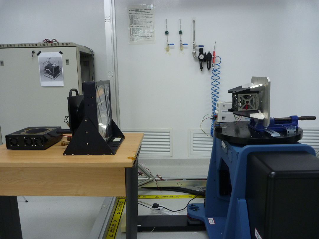
On this page, the term sun sensor refers to an electronic, photo-sensitive device that is tuned to perceive sunlight from which the direction of the sun can be estimated. These sun sensors are used on satellites, for instance to help to orient the solar panels towards the sun.
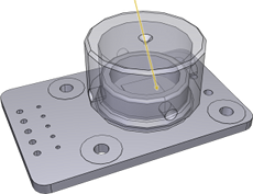
Our sun sensor consists of a 2d position sensitive detector (PSD) mounted on a printed circuit board, covered by a solid shield that has a narrow hole at the top. The hole acts as an inlet for a beam of light coming from the sun. Due to the geometry of the PSD and the hole, the sensor has a limited field of view. For instance, 35 degrees field of view. However, the field of view does not generally coincide with a cone, because the PSD is of square shape.
The sensor data processing has to solve the following two problems:
The objective of our efforts is to impove on an existing sensor calibration and data processing method that had been developped in the past. Our more recent approach compares favorably to the previous implementation:
We publish the data collected during calibration for a total of 8 different sensors. The resource files also contain the mathematical analysis in Matlab.
| Calibration data and sensor evaluation (Matlab) |
|
1.6 MB |
| Control of turn table (Matlab, with connection to mcc) * |
|
2 kB |
Sun sensors of the type described above are in use on small satellites.
You can crush the flowers,
but you can't delay spring.
Bahia Shehab
The algorithm has to map 4 numbers to a 3-dimensional vector.
The input to the algorithm are the voltages from the four channels of the PSD

The four voltage variables shall not be affected by dark current. Ideally, when the sensor is in darkness, the four voltages have the value 0.
According to the datasheet of the 2d position sensitive detector, the coordinate of the beam spot is conceptually of the form (up to scaling to a metric unit)
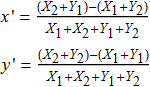
To account for the geometric alignment of the PSD we introduce four calibration constants:

The following linear transformation aligns the PSD coordinate system with the satellite coordinate system. A constant proportional to the height of the top plate determines the overall scaling.

The resulting 3-dimensional vector is the direction of the beam. If desired, the vector can be normalized.
Luck is a matter of preparation meeting opportunity.
Oprah Winfrey
The purpose of the calibration procedure is to establish the sensor response in controlled input conditions, and from there to derive the optimal calibration constants.
We use a high precision turntable to systematically sweep across the beam directions that are relevant to the sensor:
The calibration procedure for sensor #1 to #4 was conducted by the previous developpers. The bias voltage of these sensor recordings is already incorporated in the channel data. We apply the our calibration method to the channel data.
The recordings and analysis of sensors #5 to #10 are new.
| Calibration constants | Sensor characteristics |
|---|---|
sensor #: 1 biasvolt: 0.000000 [V] height : 2.500000 angle : 1.145916 [deg] offset x: 0.027853 offset y: 0.001579 | 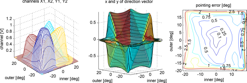 |
sensor #: 2 biasvolt: 0.000000 [V] height : 1.086000 angle : -0.572958 [deg] offset x: 0.036862 offset y: 0.062474 |  |
sensor #: 3 biasvolt: 0.001300 [V] height : 2.580000 angle : 0.000000 [deg] offset x: 0.073272 offset y: 0.016969 | 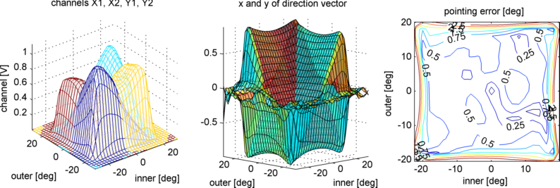 |
sensor #: 4 biasvolt: 0.002000 [V] height : 1.130000 angle : 0.000000 [deg] offset x: 0.042998 offset y: 0.066705 | 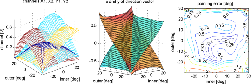 |
sensor #: 5 biasvolt: 2.020000 [V] height : 1.350000 angle : -1.300000 [deg] offset x: 0.022287 offset y: 0.045625 | 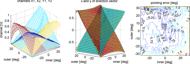 |
sensor #: 6 biasvolt: 2.020000 [V] height : 1.710000 angle : -1.700000 [deg] offset x: 0.028046 offset y: 0.039159 | 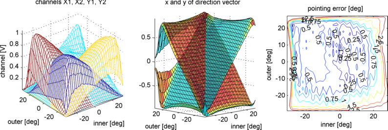 |
sensor #: 7 biasvolt: 1.998000 [V] height : 1.180000 angle : 0.000000 [deg] offset x: -0.064927 offset y: 0.018369 | 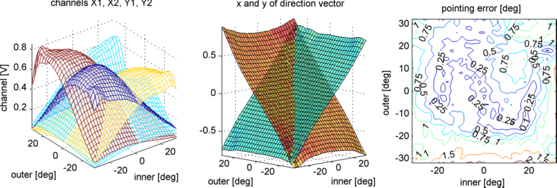 |
sensor #: 8 biasvolt: 2.021000 [V] height : 2.700000 angle : 4.000000 [deg] offset x: 0.043960 offset y: 0.031949 | 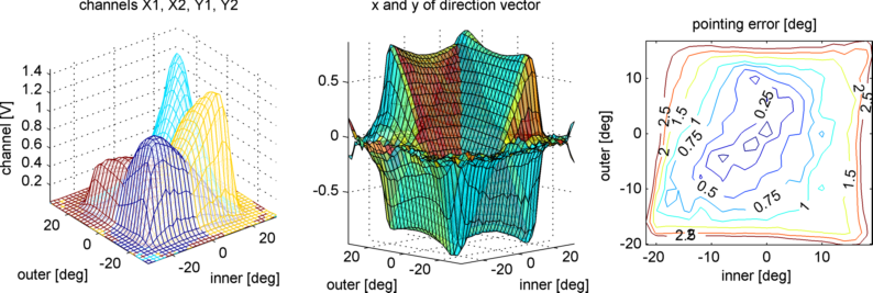 |
sensor #: 9 biasvolt: 1.998000 [V] height : 1.180000 angle : 0.000000 [deg] offset x: -0.067349 offset y: 0.016575 | 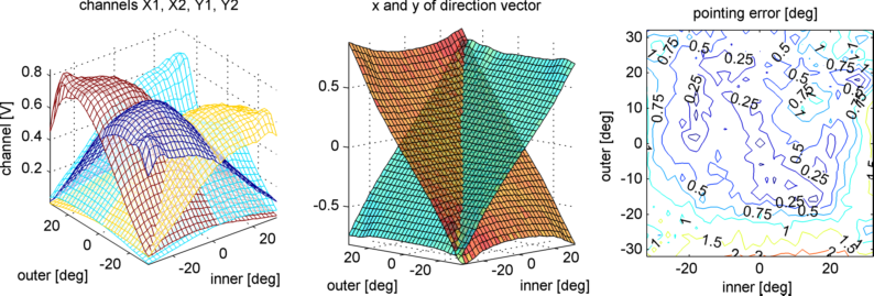 |
sensor #: 10 biasvolt: 1.998000 [V] height : 1.460000 angle : 4.000000 [deg] offset x: -0.040125 offset y: -0.012867 |  |
You can't deny that even if you used both hands.
Red Queen to Alice
The sun simulator has the following properties:
The turn table receives commands via serial interface at a baud rate of 115200. Each command is terminated by a carriage return character. In order to perform the calibration sequence, only three types of commands are required:
AXI      select inner axis
AXO      select outer axis
MOV30    move selected axis to absolute orientation of 30 degrees
MOV-14   move selected axis to absolute orientation of -14 degrees
MOVn     move selected axis to absolute orientation of n degrees
The commands sent to the turntable should be physically feasible. For instance, the command sequence below produces a following error, after which the servos have to be reset manually:
AXO
MOV0
MOV30
MOV0
The commands should change the orientation only by a small increment. A delay between two commands allows the table to finish the first command before receiving the next. The command sequence below is feasible:
AXO
MOV0
 (pause for 0.4 sec)
MOV5
 (pause for 0.4 sec)
MOV10
 (pause for 0.4 sec)
...
MOV30
...
Physical strength is measured by what we can carry;
spiritual by what we can bear.