We devise a small embedded system to adjust the light emitted by a Power-LED. The micro-controller involved is manipulated either directly by switches or by a PC via serial communication. We develop an application software that compiles a slide show of photographs. During the show, we dim the ambient light created by the Power-LED in accordance with the picture shown in that moment.
On this webpage, we present a simple schematic to drive the Power-LED using a micro-controller. We state a formula that converts the RGB components of a PC color to pulse-width modulation frequencies to imitate the color with the Power-LED. All source code is available for download.
The prototype system displayed pictures that were stored on the local hard-drive. But soon, it became obvious to take the pictures from the Internet. The current software parses the galleries of fotocommunity.de, each featuring photographs of superb quality.
Many people have contributed to make this project a success: Martin Zippel has provided the Power-LED. Kalle Rosenblad has designed the optimal schematic for the components involved. Teemu Ronkka has provided several components and shown to me how to print a circuit board. Farrukh Iqbal Sheikh made the USART work. Last but not least, the photographs of the slide show are from an album of Matthias Elsdörfer.
| Power-LED software for ATmega88 (CodeVision AVR C) |
|
8 kB |
| Ambience slide show, and calibration software (Java) * |
|
1.3 MB |
Die Liebe ist das Licht des Lebens,
in der Ehe kommt die Stromrechnung.
The Power-LED consists of 4 individual LEDs: 1 red, 2 green, 1 blue. Each color can drain current up to 300mA. Greater current might damage the device. We intend to operate the individual LEDs with a micro-controller. However, the output-pins of the micro-controller cannot provide currents as high as 300mA.
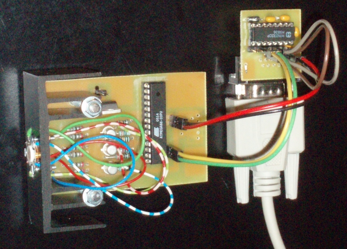
The schematic aside shows one of the LEDs in series with a 3,6Ω resistor supplied by 5V. As an electronic switch we employ the npn-transistor 2N2222A. The base of the transistor is connected over a simple network of resistors to one of the 5V output pins of the micro-controller.
For controlling, we use a ATmega88 micro-controller with an internal clock rate of 4 MHz. The micro-controller is connected to PC via serial port at a baud rate of 19200. The messages transmitted consist of 4 bytes: A header byte (=255) plus the three color values {red,green,blue} ranging from 0x00 to 0xfe each.
byte#     0    1    2    3
value  0xff  RED  GRE  BLU
In our application, we need precise timing. The micro-controller has a 16-bit (1:65536) timer, that runs independent from other commands. The timer counter overflows at a rate of 61 Hz (which is conveniently close to 50 Hz).
The following cycle is carried out about 61 times per second: Initially, all LEDs are switched off. While the 16-bit counter is far from overflowing, we check for bytes sent via serial communication. Also, we switch on a LED depending on its color value and the timer counter value. When the 16-bit timer counter is close to overflow we do nothing until the timer counter overflows.


The green led(s) does not shine as bright as the red as well as the blue led. For instance, if we open the three transistors permanently, the Power-LED will emit an overall violet hue - as opposed to white light. Thus, we develop a formula that converts the common RGB color values into the widths of the pulses to the transistors to achieve the desired ambient light.
// at the beginning RED, GRE, BLU are the computer
// screen RGB color values each between 0,...,255
RED/=14.0;
GRE/= 1.0;
BLU/=14.0;
FAC=MAX{RED,GRE,BLU};
if (FAC>0.01) {
  FAC=SQRT(255.0/FAC);
  RED*=FAC;
  GRE*=FAC;
  BLU*=FAC;
}
// finally RED, GRE, BLU are proportional to the
// pulse widths to the three 2N2222A transistors:
// 0 for constant LO, up to 255 for constant HI.
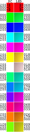
The graphics to the right compares a selection of PC color tones to photographs of the color computed with our calibatrion procedure. The light of the Power-LED was projected on a white sheet of paper. It seems that the red component is too strong for low values, but this is partially due to the properties of the digital camera.
Was ist grün und hat Räder?
Gras. Das mit den Rädern war gelogen.
For a photograph we wish to determine a representative color tone that becomes the ambient light. We investigate the following choices,
In general, the computation of the median of a data set requires sorting. However, color values are from the set {0,1,2,...,255}. In this case to find the median is O(number of pixels).
Below, we demonstrate the three different approaches. The frame around a photograph is tinted in the color corresponding to the method.
I haven't failed,
I've found 10,000 ways that don't work.
Thomas Alva Edison
We suggest to consider the following: