Together with students from all over Europe, we have participated in the field and service robotics competition 2007 held by the Otaniemi Space Agency at the Helsinki University of Technology. Our team consists of Félix Cabrera Garcia (Spain), Christelle Cartier (France), Jan Philipp Hakenberg (Germany), Timo Paavo Kalevi Heiskanen (Finland), Robertas Janickas (Lithuania), and Marco Laganà (Italy).
The objective is to equip the raw J2B2 robot with software and hardware to carry out the following mission that pretends J2B2 has just landed on planet Mars:
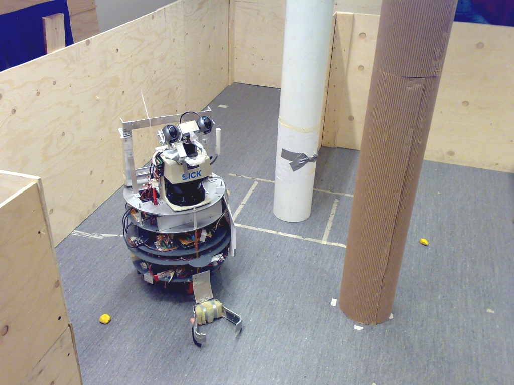
J2B2 is a castor wheeled mobile robot that is about 42 cm in diameter, and 80 cm in height. The robot comes with an odometry calculation, tactile sensors (bumpers), a laser range finder, stereo web-cameras mounted on a pan-tilt unit, and many other small features. The communication is wireless with an artificial delay of 15 sec.
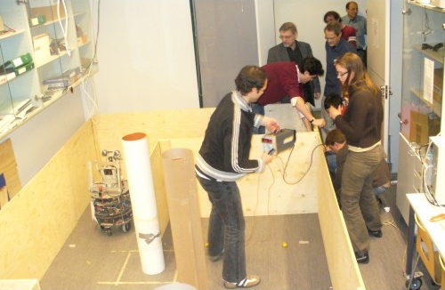
The stones are between 4-7 cm in diameter and tinted yellow. The environment is bounded by wooden panels arranged as a small labyrinth with loops and blind alleys. The floor is flat and greyish. The lander is represented by a hole in one of the panels, through which the collected stones are pushed through. The team that collects the stones fastest and returns them back to the lander while maps the area perfectly will win.
| J2B2 Mission 2007 (C using SDL) * |
|
70 kB |
| Ground station (C using SDL) |
|
5 kB |
| Density, Routing and Planning (compiled for Windows) |
|
280 kB |
Many thanks to Jari Saarinen for the technical support. His assistance was granted around the clock.
In the competition, we ranked 3rd out of 5 in total. Our robot had collected 7 out of 10 stones. The mission was carried out in an abandoned room, so it was not possible to video-record the performance. Instead, the mission was monitored using our ground station software, which was very exciting.
There is nothing more educational in robotics
than programming an actual robot.
from the book 'Probabilistic Robotics'
The central enemy of reliability is complexity.
witnessed by the many
In this section, we describe the onboard instruments that allows the robot to intercept the environment, as well as the actuators to change its state.
The SICK Laser Measurement Sensor 200 retrieves a distance profile of reflecting obstacles in a 180� field of view at a height of 50 cm above the ground. The sensor is mounted 10.5cm offset from the center of J2B2. The angular resolution is set to 1�. The measurements are accurate up to 1 cm at a systematic error of +/- 1.5 cm. The invisible laser beam is not hazardous to the human eye.
The measurements of the laser range finder become increasingly noisy for obstacles closer than 90 cm. On the other hand, material such as cloth or special plastic does not sufficiently reflect the laser beam back to the sensor. The sensor erroneously assumes a distance of 80 meters for these objects.
The maximum acceleration of J2B2 is 0.2 m/s2 on each wheel. The speed is limited by 0.5 m/s per wheel. Along with the radius of the wheels, this dictates the maximum angular rate of J2B2 to 3.8 rad/s.
Our software trims the maximum speeds further if the laser range finder detects obstacles in the vicinity of the robot. Obstacles in the front of the robot are considered more hazardous than obstacles at the same distance to the sides. These values overrule all other controls and make driving safer, for instance when following a path.

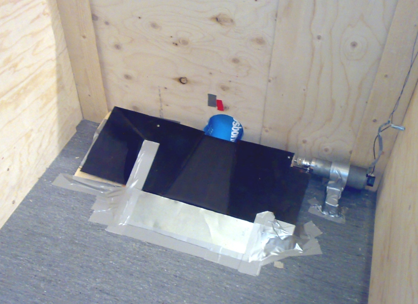
Two Logitech QuickCam Pro 5000's are mounted on a pan-tilt unit of the robot. The cameras are 13.5 cm apart, and roughly 76 cm above ground. The pictures provided have a resolution of 320 x 240 pixels each. The pan-tilt unit is a rigid frame that is oriented by servo motors. Using software commands, we can adjust the pan and the tilt of the frame that holds the cameras.
The camera images lag ca. 0.4 seconds. The images are blurry when the robot turns quickly, or the pan-tilt unit moves. From time to time, the left camera image has false colors. For better computing time, we read only the images from the right camera.
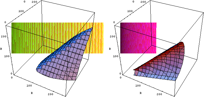
Within the images, we aim to identify yellow stones, as well as a red marker that indicates the position of the dock. Simple formulas in the red, green, and blue components of a pixel define palettes. To group the adjacent pixels, we employ the disjoint-set data structure. The algorithm is linear in the number of pixels, so that the recognition is in real time.
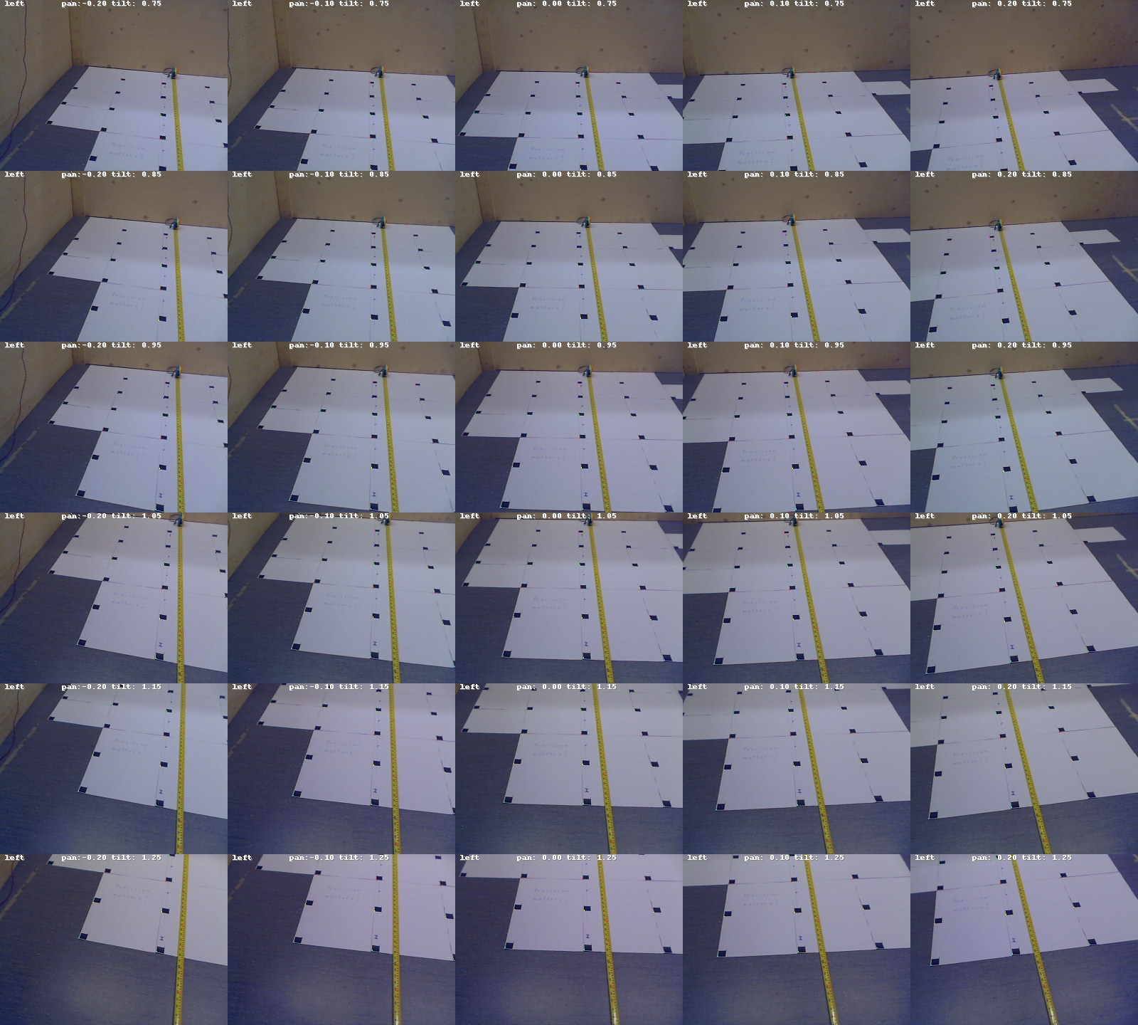
We have calibrated the cameras with great care. The coordinate transformation between pixel- and local ground-coordinates are modeled by bivariate polynomials of degree 2. The coefficients of the polynomials are determined numerically.
We aim to map a pixel location in the image of the left camera to a positional offset relative to the robot.
We denote with
 the pixel coordinate in the image, where

For better numerical treatment, we perform a simple coordinate transformation
Then, the corresponding point relative to the robot
 is given by
where the coefficients
 depend on the
pan
depend on the
pan  and
tilt
and
tilt  angles of the camera.
Our calibration procedure determines these functions.
We assume that each of
is a polynomial in
 ,
and
,
and
 of degree 2.
The coefficients of the polynomials are determined using the images to the right.
of degree 2.
The coefficients of the polynomials are determined using the images to the right.
The transformation above allows us to map features perceived in the images into the local coordinate system of the robot. Using the same mathematical model, we approximate the inverse transformation that maps local coordinates into the camera images. Many features in the head-up display employ the inverse mapping.
The coordinate transforms are accurate for pan and tilt values ranging in the vicinity of the neutral configuration. Varying the orientation of the pan-tilt unit, and consequently the cameras mounted on top, increases the ground coverage, and makes the stone detection more efficient. A simple method is keep the cameras away from walls, and to cover areas that have not been screened previously.
Nonetheless, during the mission, we do not redirect the cameras away from the neutral configuration. Moving the pan-tilt unit blurs the images for a short period of time. There was simply not enough time to design a smart yet reliable PTU control.
There are a thousand ways to point a camera,
but really only one.
Ernst Lubitsch
The provided odometry concludes the change in position from the encoders that are attached to each motor of J2B2. Because the revolution of the axes is transmitted by elastic conveyor belts the odometry computation usually lags while the robot is in motion. Naturally, any slipping of the robot goes unnoticed by the odometry. This error might accumulate to a significant defect in the position estimate after several driving maneuvres.
The position and orientation of the robot is also estimated by an on-board implementation of the monte-carlo localization method. However, the values are rarely accurate but even osciallate while the robot is in motion. The method uses an underlying map and requires an initial position.
J2B2 is a differential-drive robot with orientation and position.
We store the configuration
 of the robot in a homogeneous transformation matrix of the form
This representation is ideal to transform points and vectors between local and world coordinates.
The localization method updates the configuration via matrix multiplication
 .
To compensate numerical inaccuracies, we orthonormalize the orientation of the matrix
.
To compensate numerical inaccuracies, we orthonormalize the orientation of the matrix
 subsequently.
Both of the methods described above exhibit undesired characteristics. For that reason, we develop an algorithm for localization and mapping that is independent of the odometry and the monte-carlo method. Our solution has the following advantageous properties:
We assume the geometry is static. The laser range finder is the only sensor that contributes to the algorithm. Thus, our algorithm needs to be able to cope with the noise for obstacles closer than 90 cm, as well as the spontaneous scattering at certain angles of incidence.
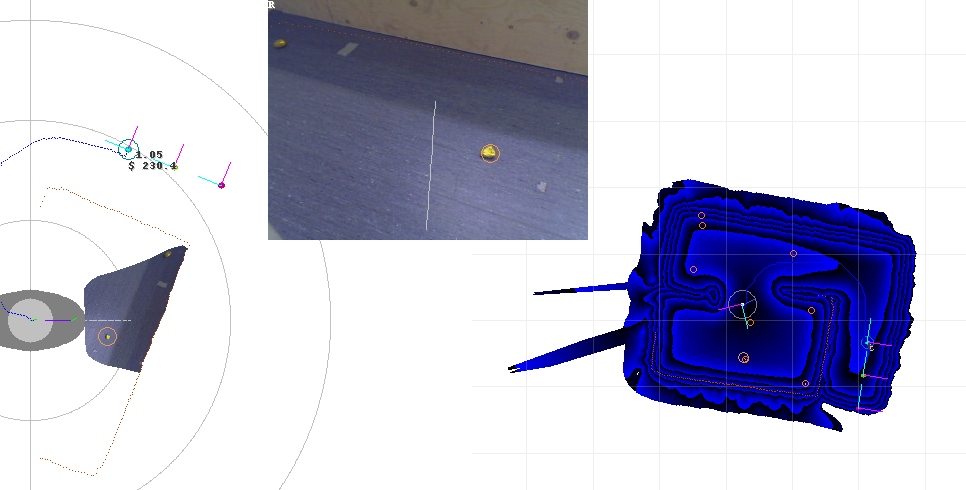
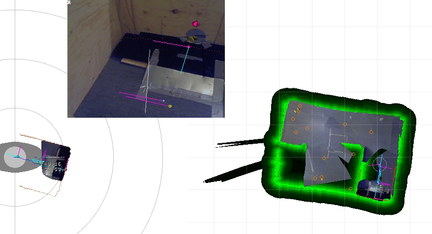
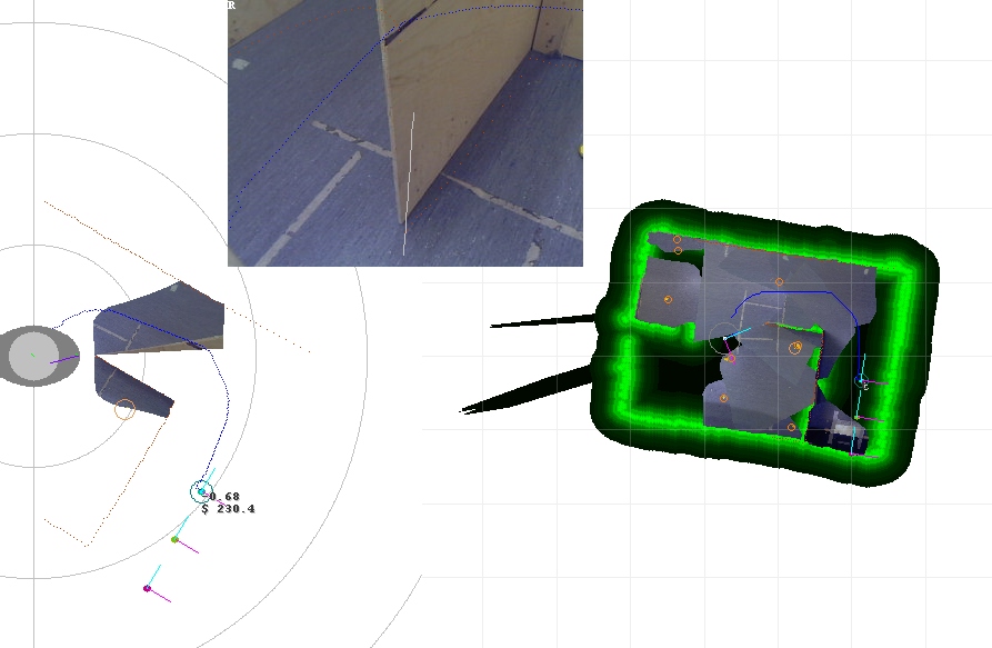
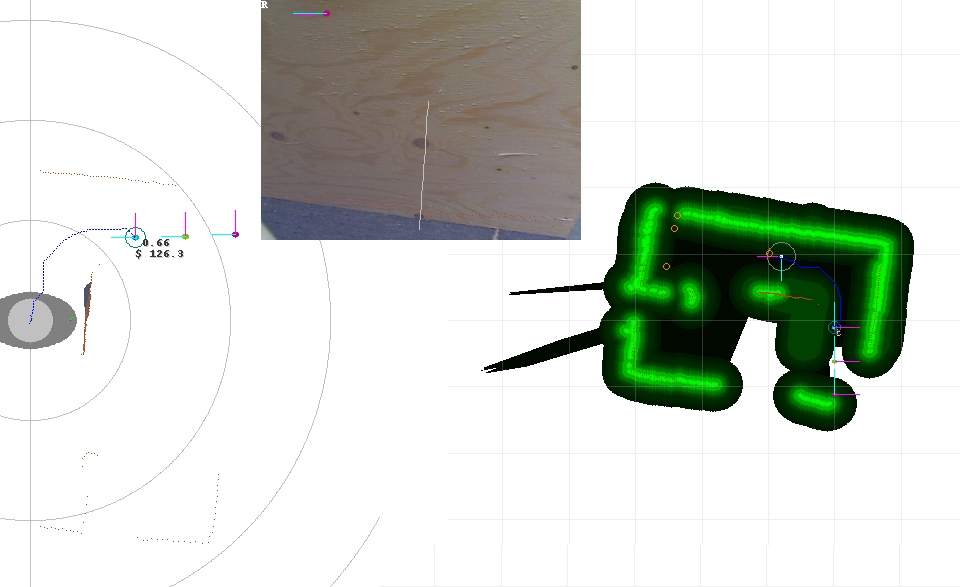
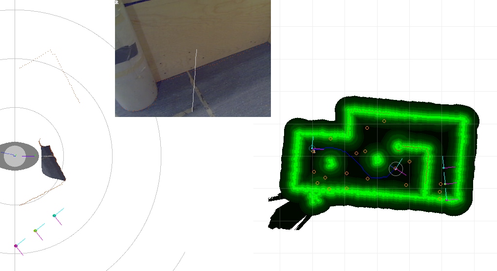
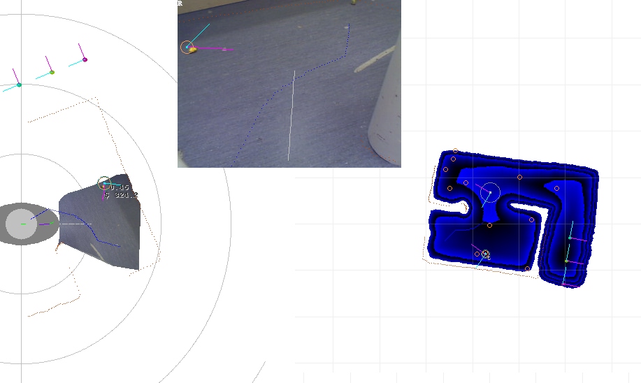
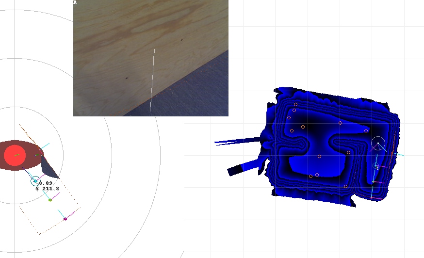
As illustrated in the pictures, obstacles perceived by the laser range finder are manifested by an increased density in their environment. The input to the localization and mapping algorithm are
The algorithm looks for the best match of the most recent laser range profile with the previous density map. In a recursive manner, the algorithm loops thru many poses in the vicinity of the previous position and orientation.
After the laser range profile is matched to the previous density map as accurately as possible, any perceived obstacles that are not represented by a high density yet manifest themselves in the update.
The maximum speeds limit the seach space. The method is very stable, however, numerically quite costly.
The output are
From the current position of the robot, we aim to find feasible paths to any point in the map.
The algorithm explores the grid iteratively. In each recursive step of the algorithm there is a layer of active vertices
However, we also route along diagonal directions.
The density function
 is sampled over a rectangular discrete grid at a resolution of 1-2 cm.
We treat this array of numbers as a graph with the following topology
is sampled over a rectangular discrete grid at a resolution of 1-2 cm.
We treat this array of numbers as a graph with the following topology
The cost to visit a vertex with coordinates
 along a vertical or horizontal edge is
, while along the diagonals
along a vertical or horizontal edge is
, while along the diagonals
 .
To increase the angular resolution even more, we add the
.
To increase the angular resolution even more, we add the
 jump of the knight.
The cost associated to a path is the integrated costs of visiting the vertices in sequence.
jump of the knight.
The cost associated to a path is the integrated costs of visiting the vertices in sequence.
This single-source shortest path problem is solved by routing shortest paths to all vertices in the graph. In each recursive step of the algorithm there is a layer of active vertices from which we visit the 16 neighbors each and compare the additional costs to the previously assumed best costs.
For each vertex, we not only store the cost of the shortest path until there, but also the adjacent vertex that preceedes along the path.
Well done is better than well said.
Benjamin Franklin
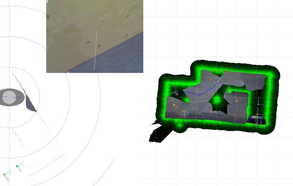
In the exploration mode, the robot is attracted by areas that have not been visited previously. We combine the projection of the camera images, the points of the laser scanner, and the previous positions of the robot into a notion of explored terrain.
Typically, the robot plans a path to a distant point in the map that belongs to the unexplored terrain. The robot drives along the path until the end, or until a stone is detected.
While driving along a path is safe, the initial alignment to the path requires some care. Since the gripper is attached in front of the robot, in some cases the longer of two possible arcs will keep the gripper away from the walls.
The robot should align and drive along a path in a quick and accurate manner. Testing has resulted in a proportional-integral-controller with the following parameters
where
 is the angle between the current heading and the direction of the path.
The graph was recorded during left and right turns.
The redish curves show
 and
and
 .
The curves on the bottom are the small deviations in position, that are ideally zero.
.
The curves on the bottom are the small deviations in position, that are ideally zero.
From the camera image and the laser range profile, the robot judges whether a stone is reachable along a straight corridor. Because the cameras are properly calibrated, and the image processing is a real-time algorithm, we aim at stones using the camera vision.
The docking maneuvre is induced when either all the terrain is explored, or at least three stones have been collected. Then, the map is routed to obtain a path that leads the robot close to the drop-off point.
Lets assume the robot has reached the vicinity of the dock. Using the camera vision the robot identifies the read marker above the dock and aligns itself to the conveyor belt. The robot approaches the dock up to a distance of 0.5 m. During this move, the stones inside the gripper are dumped on the conveyor belt. After a delay of several seconds, the robot backs up and enters the 'exploration' mode thats leads the robot away from the dock.
The communication delay of up to 15 sec renders remote control by the ground station an unattractive option. However, we create a passive ground station software for monitoring purposes. This solution requires only a minimum amount of extra work.
At intervals of 5-15 sec, J2B2 downlinks screen shots of the mission software. These images are reproduced on the computers in the control room of the Otaniemi Space Agency. Besides this 'live' feedback, the screen shots are stored as bitmaps for post-evaluation.
Measuring programming progress by lines of code is
like measuring aircraft building progress by weight.
Bill Gates
During the real mission, the robot conducted as expected for the most part. After 3 minutes, J2B2 had delivered three stones onto the conveyor belt and into the dock. By that time, a forth stone was lost on the ramp in front of the conveyor belt. After the maximum mission duration of 15 minutes, 7 out of 10 stones had beed collected.
We summarize the unexpected events that occurred during the mission:
Most of the issues are addressed in the follow up project on human interaction.
A scholar who cherishes the love of comfort
is not fit to be deemed a scholar.
Lao-Tzu
